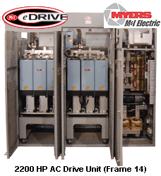
M&I eDrive AC drives are designed for the unique requirements of land and offshore drilling operations and marine industries.
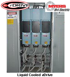
- 3 Phase 6 Pulse AC drives through 2000 HP; liquid cooled through 4000 HP
- 3 Phase 12 Pulse AC drives through 2000 HP incorporating dual winding transformers for input into converters; liquid cooled through 4000 HP.
M&I eDRIVES – 6, 12, 18 or 24 Pulse Up to 4000 HP
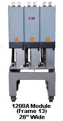
M&I’s compact AC variable speed drives (variable frequency drives) feature a roll out power module design. Air-cooled units are offered in 270A—2200A capacities and liquid-cooled versions are available through 4000A.
eDrives Offer
- Advanced AC drive technology using Eaton FX9000 7th generation technology
- 12 Mbps communication speed over fiber optic connection
- 1200A version offers a compact 32” wide x 30” deep cabinet
- Over voltage and under voltage stall protection
- Ambient compensated, auto power reduction upon over temperature and overload
- Communication capabilities include Ethernet, Device net, Profibus, & CAN bus
- Voltage capacity through 690 VAC
- Roll-out power module design for fast replacement
- Over voltage protection
- Under voltage protection
- Ground fault protection
- Motor phase supervision
- Over current protection
- Unit over temperature protection
- Motor overload protection
- Motor stall protection
- Motor under load protection
- Short circuit protection of +24V and +10V reference voltages
- 300—1500 HP at 460 VAC and 450—4000 HP at 690 VAC ratings
- Overload of 150% for 60 sec
- Peak Current: Is for 2 sec every 20 sec
- Output Frequency of 0—320 Hz
- Control Method:
- Frequency Control V/f
- Open Loop: Sensor-less Vector Control
- Closed Loop: Frequency Control
- Closed Loop: Vector Control
- Ambient Operating Temperature
- -10° C to 40° C: IH
- -10° C to 40° C: IL
M&I’s eDrives feature a standard non-regenerative front end that can easily support a multi-pulse configuration for reduced harmonics. A fully-regenerative front end is also available as an option. Our AC Drives are available in both a single and multiple VFD configurations with common DC bus for multiple inverters.
The inverter mechanically consists of two units, the Power Unit and the Control Unit. The Power Unit contains an inverter bridge which consists of IGBT switches and produces symmetrical, three-phase PWMmodulated AC voltage to the motor.
The control unit is a high performance microprocessor with keypad and PC serial interface. The microprocessor controls the motor based on the information it receives through measurements, parameter settings, control I/O and the control keypad. The motor and application control block controls the motor control ASIC which, in turn, calculates the IGBT states.
Gate drivers amplify these signals for driving the IGBT inverter bridge. The control keypad constitutes a link between the user and the inverter. The control keypad is used for parameter setting, reading status data and giving control commands. It is detachable and can be operated externally and is connected via a cable to the inverter. Instead of the control keypad, a PC can be used to control the inverter if connected through a similar cable.


